Patient Situation: When the Default Options Were Already Off the Table
Ridge condition
The alveolar bone height following extraction had resorbed to a degree that placed implant placement outside the acceptable risk range. While the prescribing dentist did not provide a radiographic measurement, the treatment planning notes indicated that vertical augmentation would have been required, and the patient had declined the extended timeline and cost associated with bone grafting procedures.
Abutment evaluation
The adjacent natural teeth could not serve as abutments for a traditional three-unit fixed bridge. The prescribing dentist’s examination noted compromised periodontal support bilaterally, with clinical attachment levels and mobility readings that fell below the threshold for predicta
ble long-term loading. A fixed prosthesis supported by those abutments would have transferred occlusal forces to teeth already at the margin of stability.
Kennedy classification
Class III — a bounded edentulous span with teeth remaining both anterior and posterior to the defect. This classification matters because it ruled out the most problematic flexible partial scenario: the free-end saddle with no distal abutment (Kennedy Class I), where a flexible base has nothing to seat against and will load the ridge unevenly.
Functional loading
The anterior location meant the prosthesis would encounter primarily incising forces rather than sustained masticatory load. This is the one scenario where the tissue-borne, non-rigid design of a flexible partial does not work against itself — a posterior span would concentrate stress and delaminate under the lateral and vertical forces of chewing.
Patient expectation
The prescribing dentist had outlined the tradeoffs explicitly before fabrication: a removable appliance with esthetic clasp design and no metal display, in exchange for accepting tissue support rather than tooth support, and understanding that the prosthesis could not be relined. The patient agreed, with the implant option left open for future consideration if ridge augmentation became acceptable.
Dentist Requirements: What the Prescription Specified
The prescription for this case came with specific design instructions, which is the exception rather than the rule — most anterior flexible cases arrive with only tooth numbers, shade, and “flexible partial” written on the lab slip. When a prescription specifies design parameters, it signals that the dentist has surveyed the diagnostic casts and identified the path of insertion, undercut locations, and clasp positions that will work. When it does not, we survey the casts ourselves and return a proposed design for confirmation before we process.
This prescription included:
1. Measured interocclusal clearance The dentist provided a measurement in the anterior segment, recorded at the proposed denture tooth positions. This is critical because Valplast resin does not chemically bond with acrylic resin denture teeth — the teeth must be retained mechanically, typically with drilled holes or retention wings, and that requires space. Manufacturer guidelines state minimums of 4 mm for an all-flexible design and 6 mm where a metal framework is combined, but these figures are published for posterior segments. No established minimum exists for the anterior segment, so we ask for the measured value rather than applying a posterior standard by default.
In this case, the available clearance was within the range that allowed standard denture tooth selection and mechanical retention without opening the vertical dimension.
2. Clasp design preference The dentist specified low-spur clasps positioned 1 mm supragingivally on the adjacent teeth. Among the four clasp designs Valplast manufacturers document — wrap-around, high-spur, low-spur, and split — the low-spur configuration keeps the clasp tip above the free gingival margin when the tooth inclination and available undercut permit it. This was an esthetic decision: the clasp arm would be visible if the patient pulled the lip back, but it would stay out of the smile line during normal conversation and at rest.
The alternative — a wrap-around clasp extending into the interproximal embrasure — would have been less visible from the facial but would have risked gingival blanching if the patient’s smile line was high. The dentist chose the compromise that fit this patient’s anatomy and esthetic tolerance.
3. Relief and tissue extension The prescription called for conservative palatal coverage, limited to the area required for retention and stability, rather than extending the flange to the maximum the material could span. This is a deliberate tradeoff: more tissue contact improves retention, but it also increases the surface area in contact with the gingival margin, and one of the documented concerns with flexible partials is that elastic clasps may extend to or encroach upon the gingival margin (PMC7654199).
Specific relief was marked at the incisive papilla and over any prominent rugae that would have caused pressure points during seating.
4. Surveyed path of insertion
The dentist provided articulated diagnostic casts with the path of insertion marked. This is not standard practice for every laboratory, but it is the practice we prefer, because the path determines which undercuts are usable and which must be blocked out. A flexible partial inserted along the wrong path will either fail to engage the retention, or it will engage and then strip the clasp arm during removal.
5. No framework
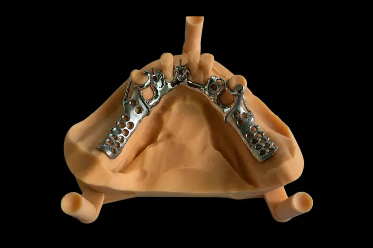
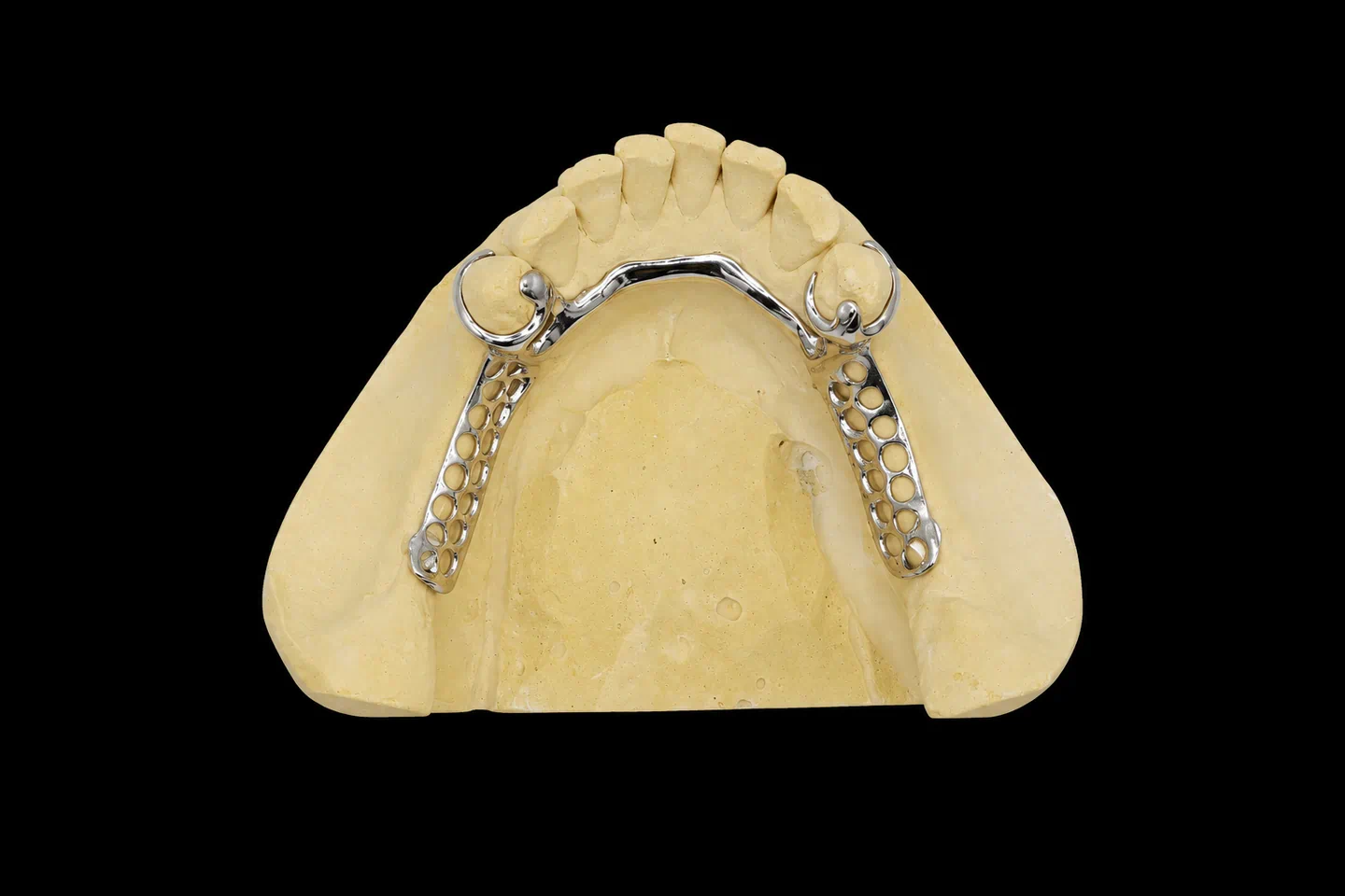
The prescription specified an all-flexible design rather than a hybrid with a cast cobalt-chrome framework. We build both, and the hybrid exists for one reason: the anterior segment often needs a flexible clasp for esthetics and a rigid framework for support, and neither an all-flexible base nor an all-metal partial delivers both. But in this case, the span was short enough and the loading light enough that a framework was not required. The dentist made that call, and we agreed.
How We Met Requirements: Design Decisions and the Alternatives We Gave Up
Survey and retention planning We mounted the diagnostic casts on a surveyor and confirmed the path of insertion the prescribing dentist had marked. The adjacent abutment teeth presented usable undercuts at approximately 0.25 mm depth when measured with a 0.25 mm undercut gauge at the height of contour. This is within the range a flexible clasp can engage without excessive force during insertion or removal.
The low-spur clasp design the dentist specified would originate from the denture base, travel gingivally along the facial surface, and engage the undercut 1–2 mm above the gingival margin. The terminal third of the clasp would flex during insertion and then return to engage the undercut once the prosthesis was fully seated.
What we gave up
A deeper undercut (0.50 mm) would have improved retention, but the anatomy presented a choice: either accept the 0.25 mm undercut as-is, or prepare a composite build-up on the facial surface to create an artificial undercut closer to the desired depth. The prescribing dentist elected to use the natural undercut, which meant accepting moderate retention rather than maximum retention. This was the correct compromise for an anterior case where the patient would be removing and inserting the prosthesis daily — excessive retention translates to difficult insertion, and patients abandon appliances they cannot seat comfortably.
Denture tooth selection and mechanical retention
We selected anterior denture teeth from the Ivoclar Vivadent Phonares II series, sized to match the prescrib
ed shade and mold, and compatible with the available interocclusal space. Each tooth was prepared with three 1.2 mm retention holes drilled through the cervical third of the tooth on a slightly divergent axis. These holes would be filled with Valplast resin during injection molding, creating a mechanical interlock.
Retention hole diameter and placement follow the manufacturer’s technical manual rather than our own empirical standard, because Valplast International has published the relationship between hole geometry and pull-out force for their resin formulation. The resin does not bond chemically to acrylic; the retention is purely mechanical, and insufficient hole depth or diameter has been a documented cause of denture tooth displacement in service.
What we gave up
An alternative retention method — embedding the denture teeth with extended horizontal flanges or wings — would have distributed retention load over a larger surface area, but it requires more vertical clearance than drilled holes. The measured space in this case permitted holes but not wings. We designed to the space we had.
Clasp positioning and margin control
The low-spur clasps were waxed to terminate 1 mm above the free gingival margin on the facial surfaces of the adjacent abutments, as specified. This 1 mm clearance is a design target, not a manufacturing tolerance — the actual as-finished position can vary by ±0.5 mm depending on how the wax-up translates through investment and injection.
During finishing, we verified clasp position on the master cast and adjusted the clasp tips with a carbide bur and light polishing to ensure the terminal contact sat at the intended height. Clasps that extend onto or below the gingival margin can cause chronic blanching, gingival recession, and patient discomfort — and in anterior cases, they are visible, so the patient will notice and report them immediately.
What we gave up
Positioning the clasps entirely interproximally, hidden from facial view, would have been the most esthetic solution. But interproximal placement requires undercuts in the embrasure spaces, and this case presented undercuts on the facial surfaces instead. We designed to the anatomy rather than forcing a design the anatomy would not support.
Base extension and palatal coverage
The denture base was extended to cover the edentulous ridge fully, with flanges contoured to the depth of the vestibular sulcus and palatal contours limited to the area required for retention. The prescribing dentist’s instruction — “conservative palatal coverage” — meant we stopped the palatal extension short of the junction between hard and soft palate, rather than carrying it distally for maximum contact.
This decision has a tradeoff: less tissue contact means less retention, but it also means less surface area in chronic contact with the palatal mucosa. One of the concerns raised in the literature about flexible partials is that tissue-borne loading can overload the supporting mucosa (PMC7654199), and limiting coverage is one way to control the contact pressure per unit area.
What we gave up
Maximum retention. An all-flexible partial relies on tissue contact and elastic clasp engagement for retention — it has no occlusal rests, no reciprocation, and no rigid major connector to distribute force. Reducing palatal coverage reduced the total retention, which meant the patient would need to use greater care during insertion and removal. The dentist accepted that tradeoff in favor of reducing long-term mucosal loading.
Framework decision: all-flexible versus hybrid
This case was designed as an all-flexible Valplast prosthesis with no metal framework. We build both all-flexible and hybrid designs (a cast cobalt-chrome framework with flexible clasps into the anterior segment), and the choice depends on three factors:
In this case:
All three factors favored the all-flexible design, so that is what we fabricated.
What we gave up: A hybrid design with a lingual metal framework would have provided greater rigidity, more predictable occlusal stability, and better load distribution to the abutment teeth. But it would also have introduced a palpable lingual bar or plate, required a longer laboratory sequence (wax-up, casting, finishing, clasp attachment), and cost the patient the all-flexible esthetics they wanted. The prescribing dentist made the call that in a short anterior span with light loading, the hybrid was solving a problem this case did not have.
Design Outcome: What We Delivered
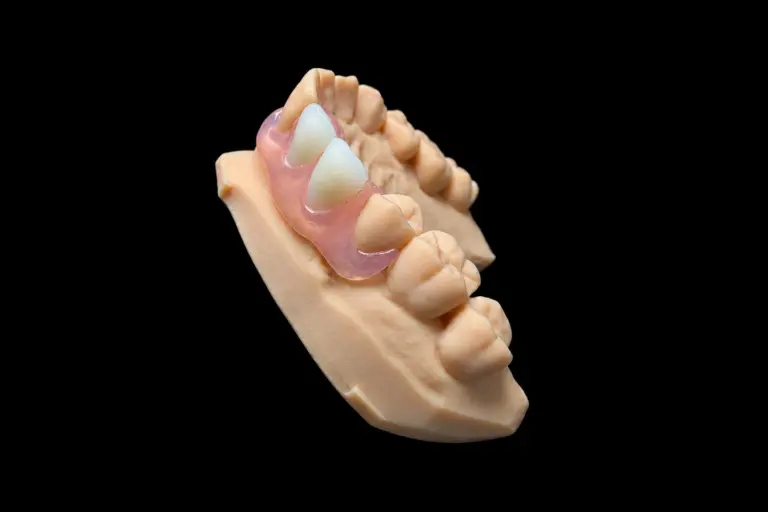
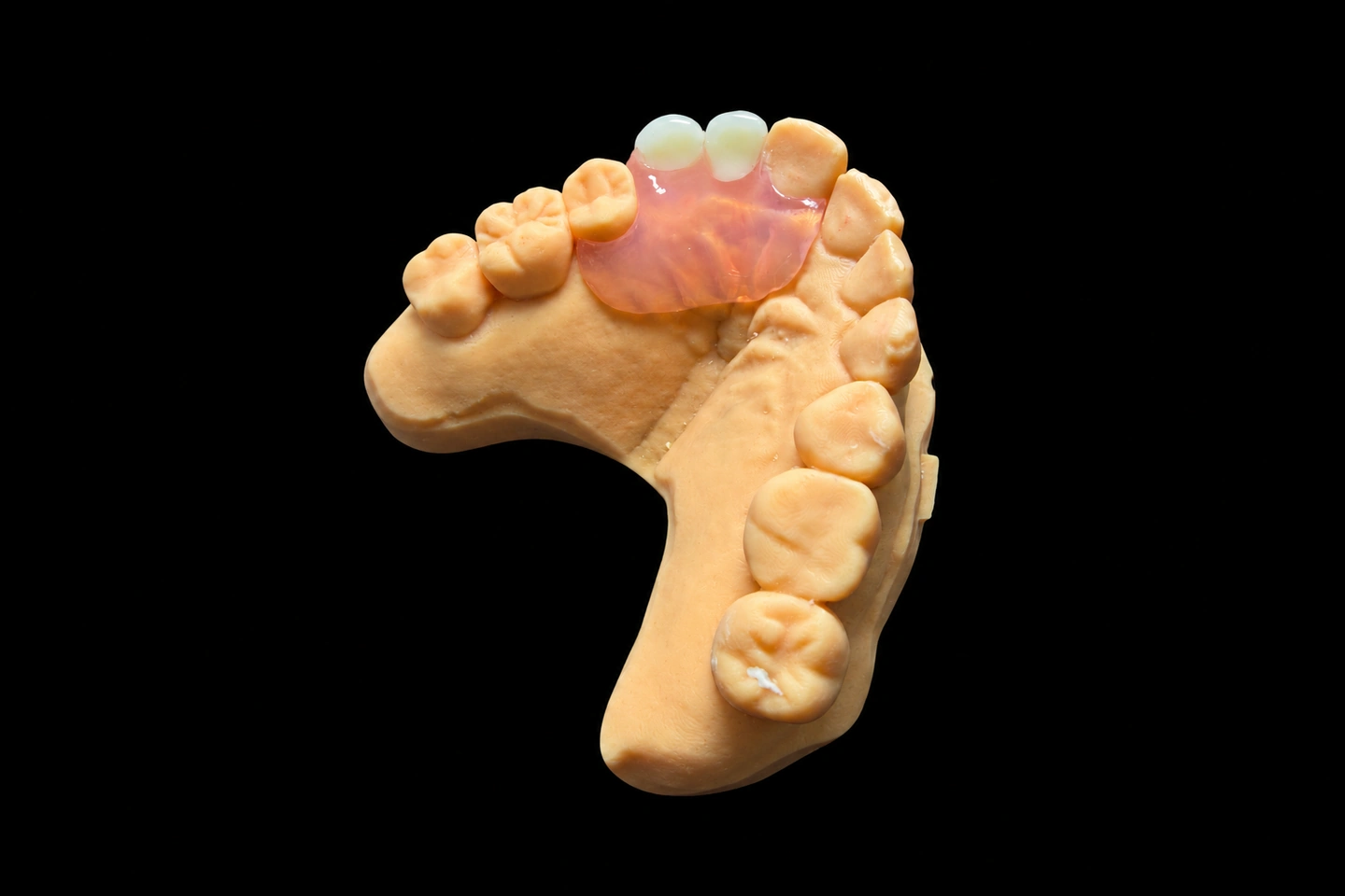
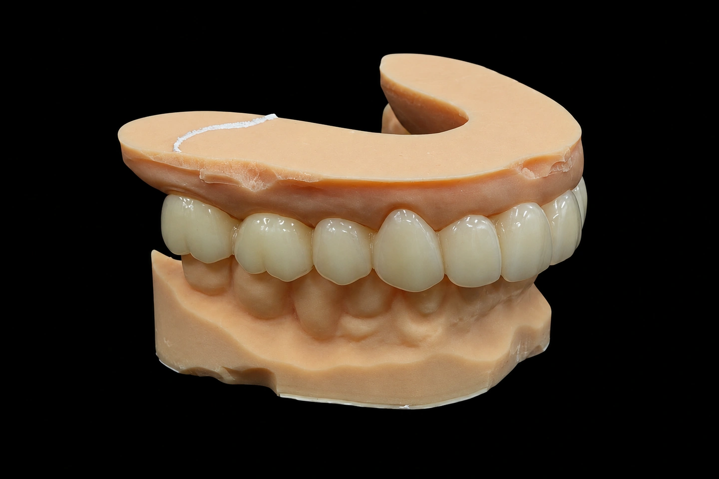
The finished prosthesis was a two-to-three-tooth maxillary anterior Valplast flexible partial with the following specifications:
Insertion and delivery
The prescribing dentist reported at delivery that the prosthesis seated fully with moderate finger pressure, the clasps engaged the abutment undercuts without visible blanching, and the patient could remove and reinsert the appliance without difficulty. No immediate adjustment was required.
Follow-up interval
This case was reviewed by the prescribing dentist at an interval the dentist did not disclose to us. We do not track follow-up as a laboratory; that responsibility belongs to the prescribing practice. Where a dentist volunteers follow-up observations, we document them. Where they do not, we say so.
What to Put on the Prescription
Ten items. The first four decide whether the case is buildable; the rest decide whether it fits.
Items 1–4 come back to you as a query if they are missing. We would rather lose two days at the start than rebuild the case.
Send a Case
If you have an anterior case where the ridge will not take an implant and the abutments will not carry a bridge, send it. If you are not sure the material is defensible, send the situation without the case — tooth numbers, clearance, and a photograph — and we will tell you whether we would build it.
We will say no when the answer is no. That is the part of this page worth testing.
Trademark Notice Valplast® is a registered trademark of Valplast International Corp. We are an independent dental laboratory and are not affiliated with, authorised by, or endorsed by the trademark owner. Material names are used descriptively to identify the prosthesis requested on the prescription.